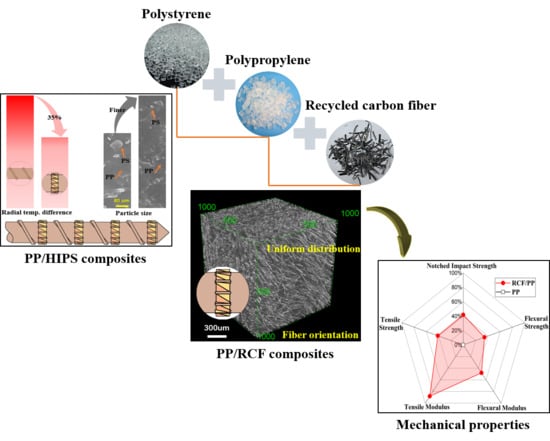
Enhancing Mixing and Thermal Management of Recycled Carbon Composite Systems by Torsion-Induced Phase-to-Phase Thermal and Molecular Mobility


Abstract
:
1. Introduction
2. Experimental
2.1. Materials
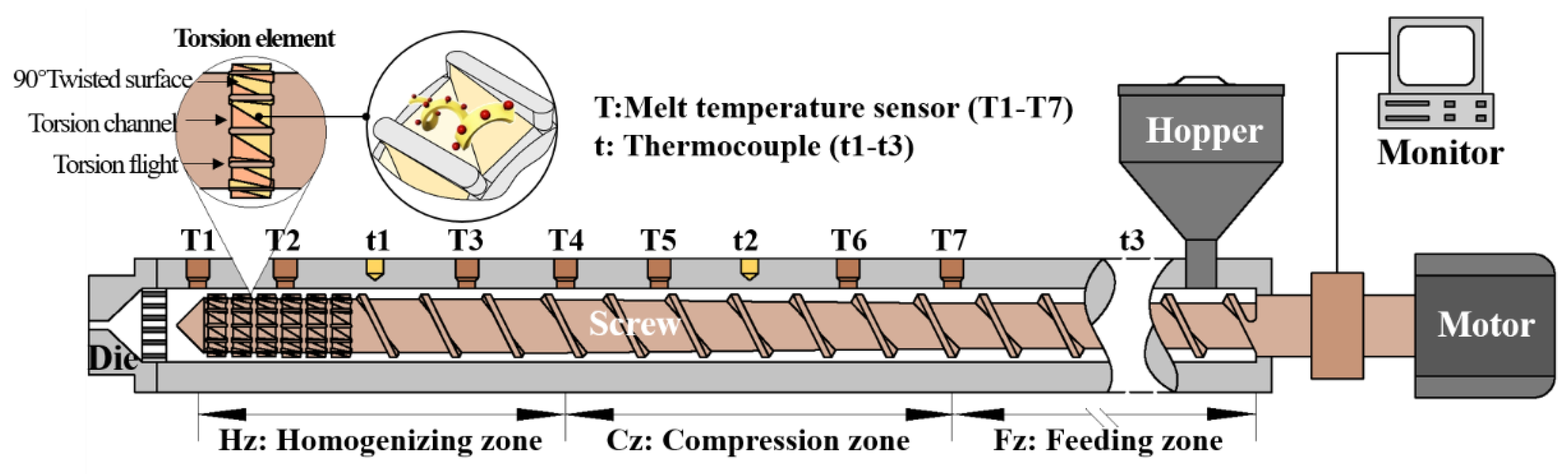
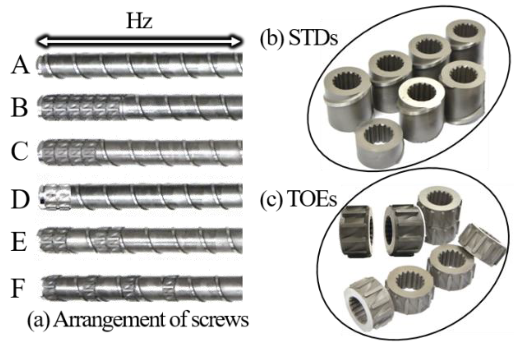
2.2. Test Stand and Torsion Element
2.3. Characterization
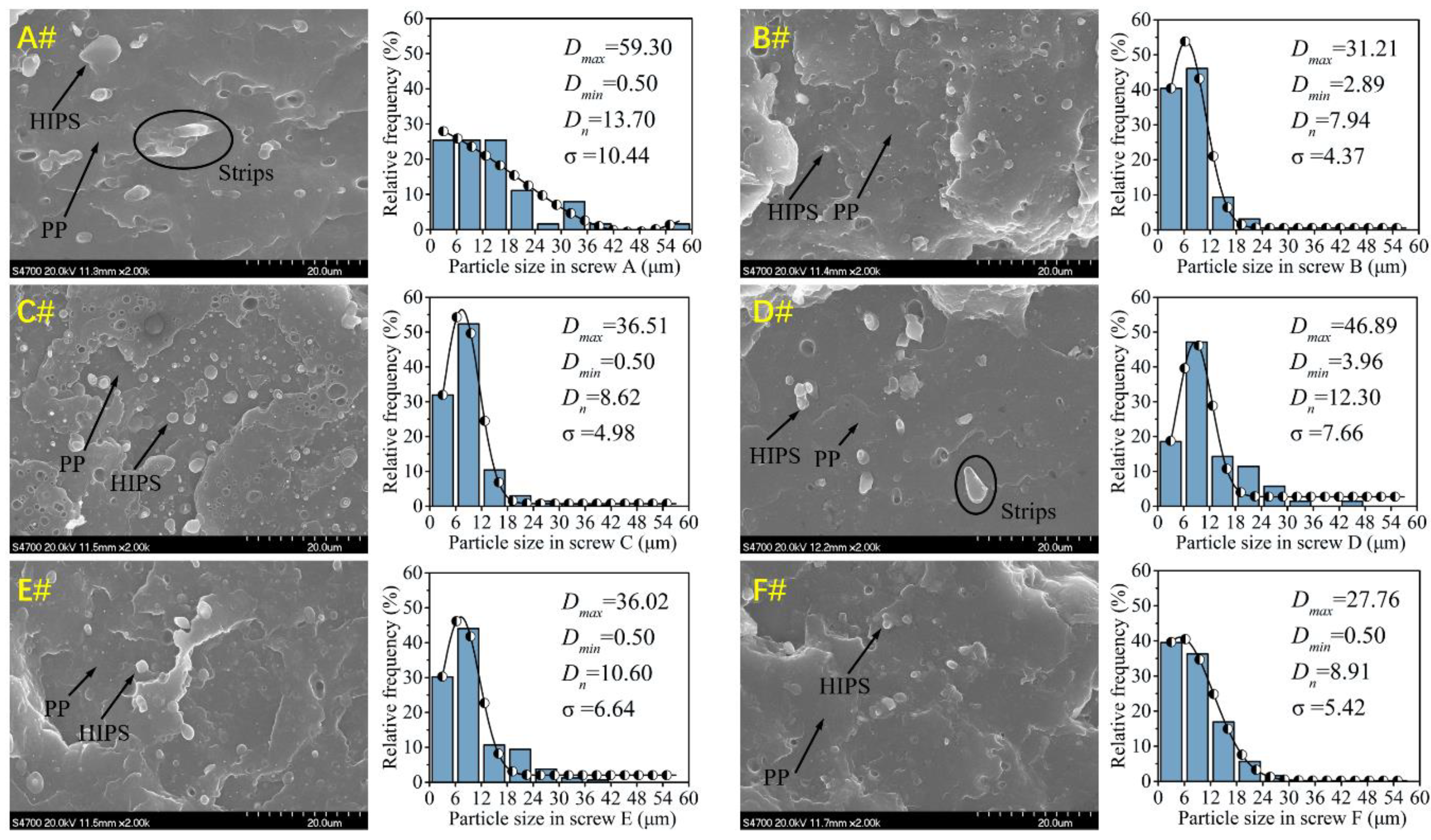
2.3.1. Size Measurement of Dispersed Phase in Extrudates
2.3.2. Heat Transfer Property
3. Results and Discussion
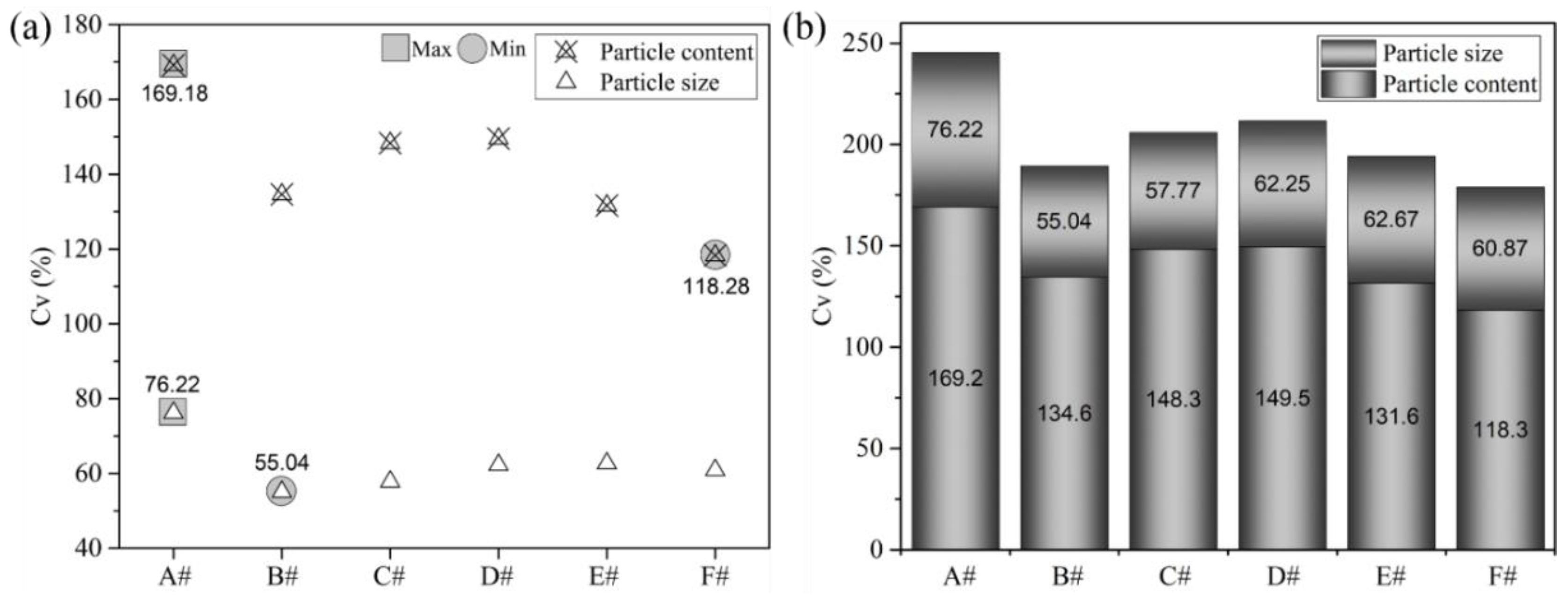
3.1. Mass Transfer and Mixing Characteristics
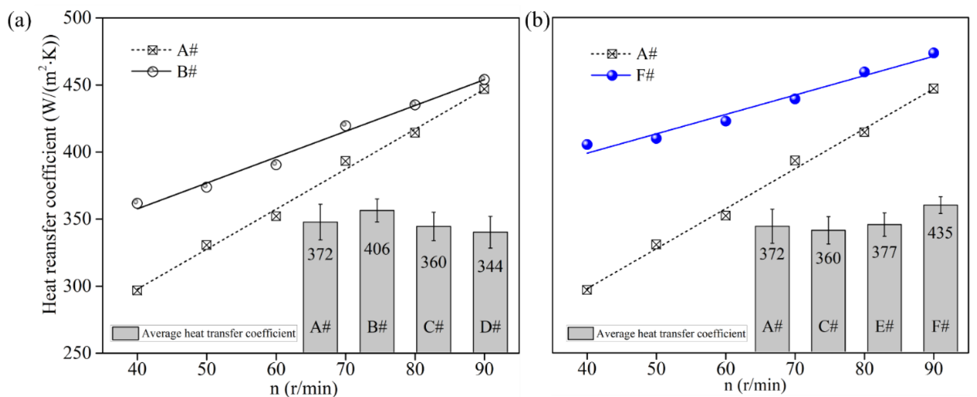
3.2. Heat Transfer Property
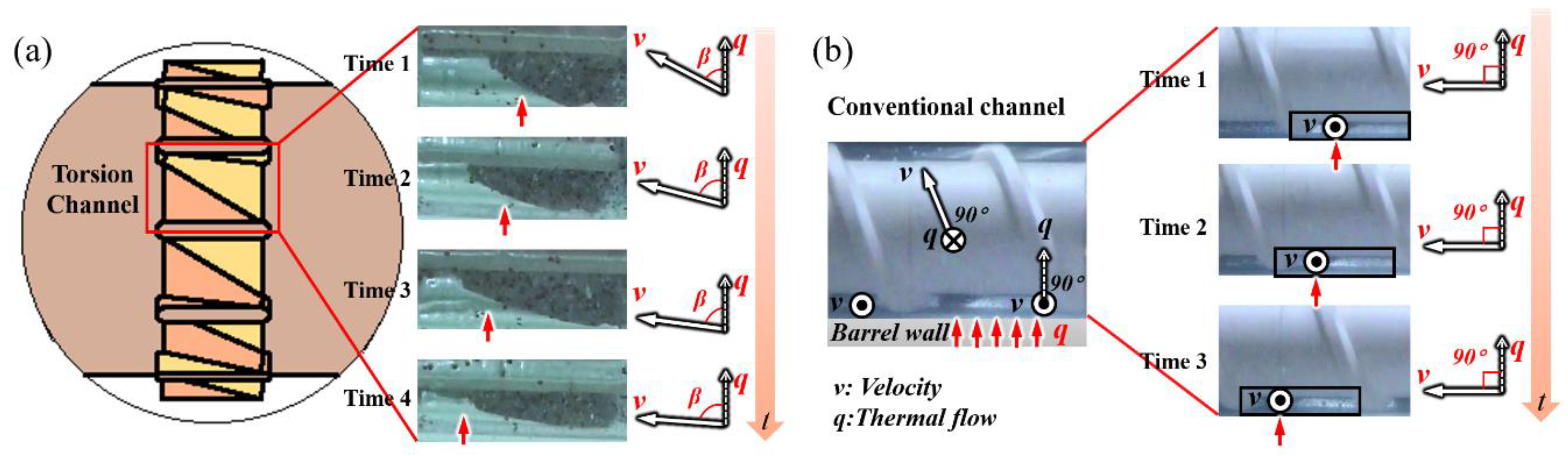
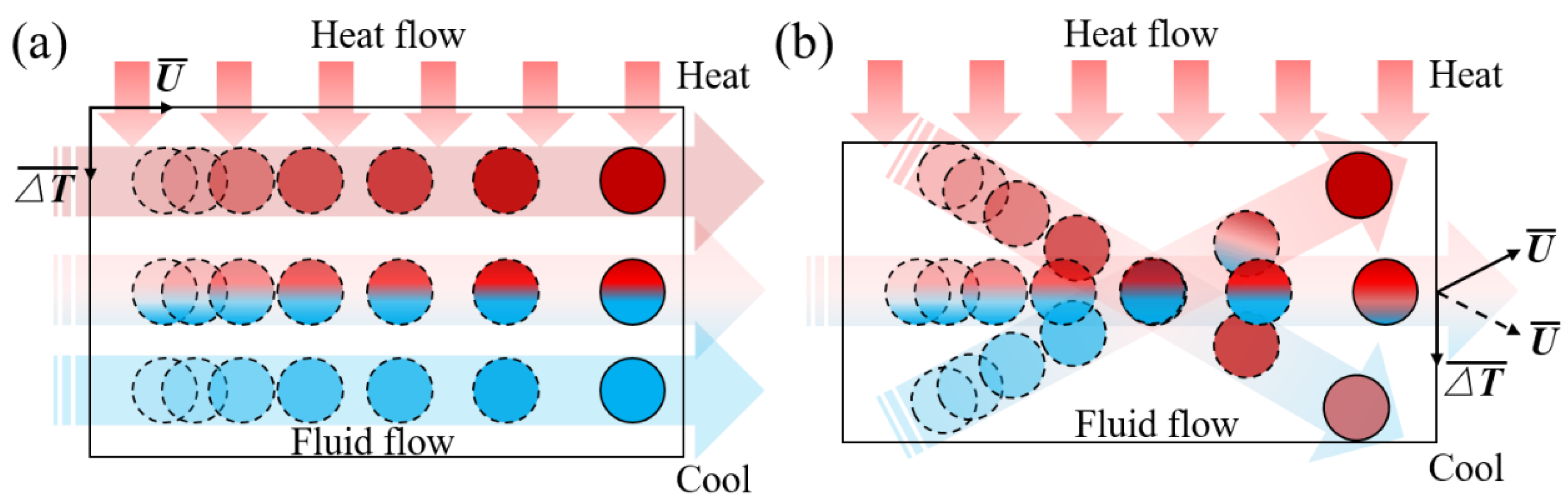
3.3. Fluid Flow Characteristics and Heat Transfer Mechanism
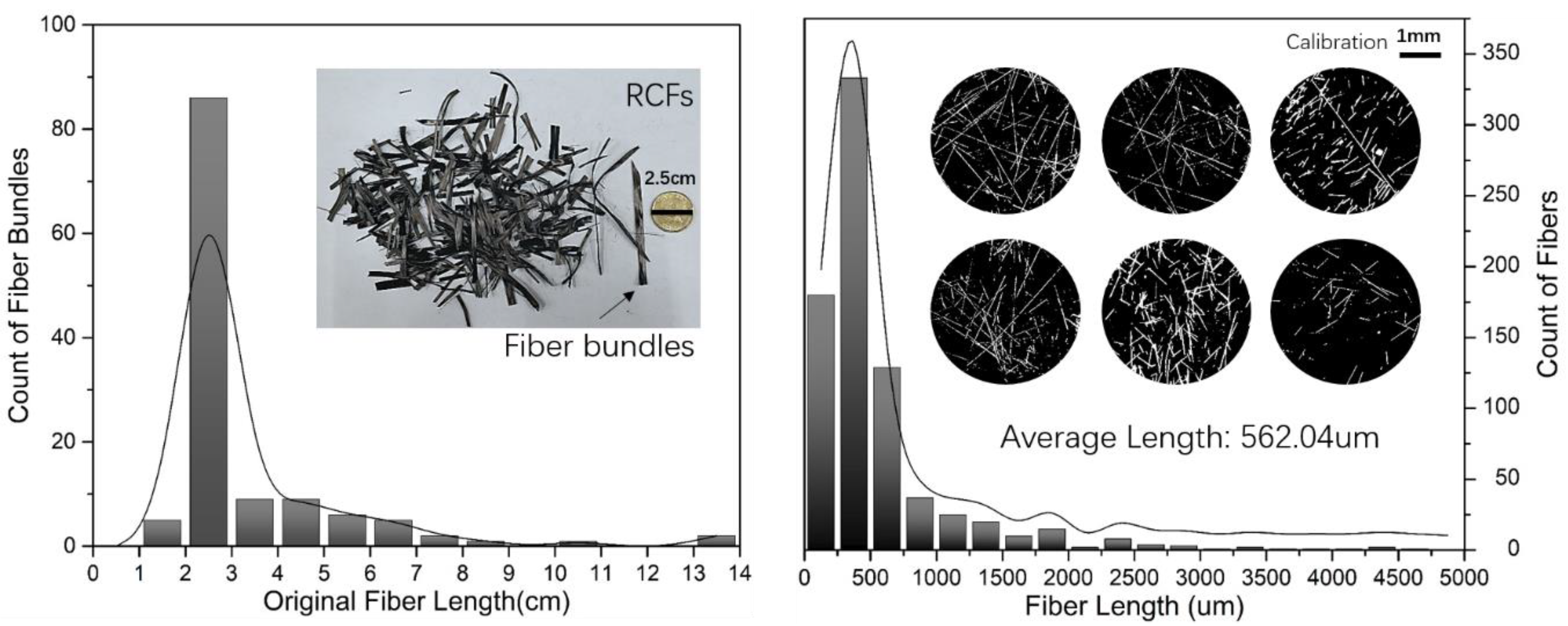
3.4. Reclaimed Carbon Fiber (RCF)-Based Composites
3.4.1. Fiber Orientation and Distribution
3.4.2. Crystallization Behavior
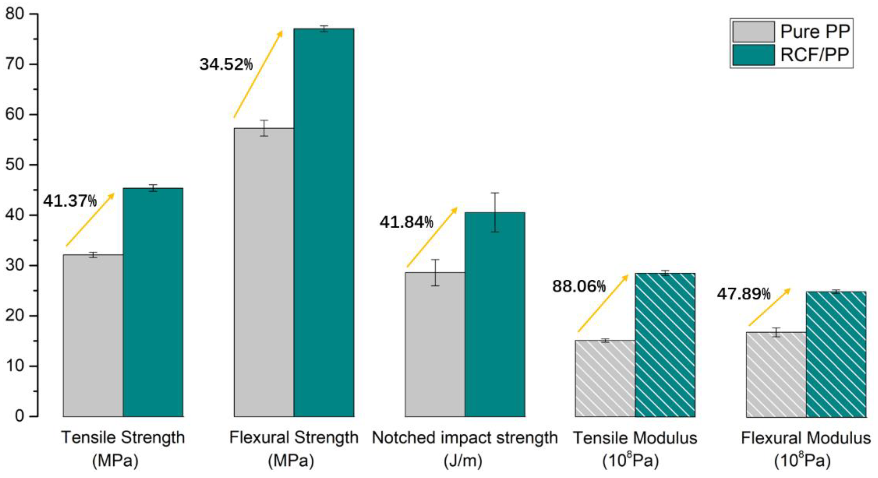
3.4.3. Mechanical Properties
4. Conclusions
Supplementary Materials
Author Contributions
Funding
Acknowledgments
Conflicts of Interest
Nomenclature
| t | = mean residence time: min |
| Ms | = total weight of extrudates after stopping feeding, kg |
| Qh | = flow rate of extruder, kg/min |
| Dn | = number average particle size, μm |
| Cv | = coefficient of variation |
| σ | = standard deviation |
| μ | = average value |
| Q | = heat transfer power, W |
| A | = heat transfer area, m2 |
| T | = melt Temperature, °C |
| Tw | = wall temperature, °C |
| α | = convective heat transfer coefficient, W/(m2·°C) |
| Re | = Reynolds number |
| Pr | = Prandtl number |
| Nu | = Nusselt number |
| = velocity vector | |
| = temperature gradient vector | |
| β | = field synergy angle |
References
- Potente, H.; Többen, W.H. Improved Design of Shearing Sections with New Calculation Models Based on 3D Finite-Element Simulations. Macromol. Mater. Eng. 2002, 287, 808–814. [Google Scholar] [CrossRef]
- Sikora, J.W.; Samujlo, B. Investigation of the poly(vinyl chloride) extrusion process using a feed throat with a feed pocket. Polym. Eng. Sci. 2014, 54, 2037–2045. [Google Scholar] [CrossRef]
- Abeykoon, C.; Kelly, A.L.; Brown, E.C.; Coates, P.D. The effect of materials, process settings and screw geometry on energy consumption and melt temperature in single screw extrusion. Appl. Energy 2016, 180, 880–894. [Google Scholar] [CrossRef] [Green Version]
- Kelly, A.L.; Brown, E.C.; Coates, P.D. The effect of screw geometry on melt temperature profile in single screw extrusion. Polym. Eng. Sci. 2006, 46, 1706–1714. [Google Scholar] [CrossRef]
- Rauwendaal, C. New developments in mixing and screw design. Plast. Addit. Compd. 2008, 10, 32–36. [Google Scholar] [CrossRef]
- Huang, M.S. Design analysis of a standard injection screw for plasticising polycarbonate resins. J. Polym. Eng. 2016, 36, 537–548. [Google Scholar] [CrossRef]
- Tong, F.H.; Shi, D.L.; Qin, J.H. Single Screw Extruder Characteristics on Friction and Heat Generated with the Barrel Carved Spiral Groove. In Advanced Polymer Science and Engineering; Wang, C.H., Ma, L.X., Yang, W., Eds.; Trans Tech Publications Ltd.: Stafa-Zurich, Switzerland, 2011; Volume 221, pp. 668–673. [Google Scholar]
- Rauwendaal, C. New screw design for cooling extruders. Plast. Rubber Compos. 2004, 33, 397–399. [Google Scholar] [CrossRef]
- Karkri, M.; Jarny, Y.; Mousseau, P. Thermal state of an incompressible pseudo-plastic fluid and Nusselt number at the interface fluid–die wall. Int. J. Therm. Sci. 2008, 47, 1284–1293. [Google Scholar] [CrossRef]
- Wei, D.; Luo, H. Finite element solutions of heat transfer in molten polymer flow in tubes with viscous dissipation. Int. J. Heat Mass Transf. 2003, 46, 3097–3108. [Google Scholar] [CrossRef] [Green Version]
- Zhang, X.-H.; Ouyang, J. Meshless analysis of heat transfer due to viscous dissipation in polymer flow. Eng. Anal. Bound. Elem. 2008, 32, 41–51. [Google Scholar] [CrossRef]
- Kaushik, P.; Mondal, P.K.; Pati, S.; Chakraborty, S. Heat Transfer and Entropy Generation Characteristics of a Non- Newtonian Fluid Squeezed and Extruded Between Two Parallel Plates. J. Heat Transf.-Trans. Asme 2017, 139, 1335–1344. [Google Scholar] [CrossRef]
- Estrada, O.; Ortiz, J.C.; Hernández, A.; López, I.; Chejne, F.; del Pilar Noriega, M. Experimental study of energy performance of grooved feed and grooved plasticating single screw extrusion processes in terms of SEC, theoretical maximum energy efficiency and relative energy efficiency. Energy 2020, 194, 116879. [Google Scholar] [CrossRef]
- Wang, C.; Bussmann, M.; Park, C.B. Numerical Investigation of the Effect of Screw Geometry on the Mixing of a Viscous Polymer Melt. J. Appl. Polym. Sci. 2010, 117, 775–784. [Google Scholar] [CrossRef]
- Monchatre, B.; Raveyre, C.; Carrot, C. Influence of the melt viscosity and operating conditions on the degree of filling, pressure, temperature, and residence time in a co-kneader. Polym. Eng. Sci. 2018, 58, 133–141. [Google Scholar] [CrossRef]
- Teixeira, C.; Gaspar-Cunha, A.; Covas, J.A. Flow and Heat Transfer Along the Length of a Co-rotating Twin Screw Extruder. Polym.-Plast. Technol. Eng. 2012, 51, 1567–1577. [Google Scholar] [CrossRef]
- Dhanasekharan, K.M.; Kokini, J.L. Design and scaling of wheat dough extrusion by numerical simulation of flow and heat transfer. J. Food Eng. 2003, 60, 421–430. [Google Scholar] [CrossRef]
- Kuzyaev, I.M. Intensification of Heat and Mass Transfer Processes in the Working Channel of Extrusion Machines during Processing of Newtonian Polymer Liquids. Heat Transf. Res. 2005, 36, 359–371. [Google Scholar] [CrossRef]
- Spina, R.; Spekowius, M.; Hopmann, C. Simulation of crystallization of isotactic polypropylene with different shear regimes. Thermochim. Acta 2017, 659, 44–54. [Google Scholar] [CrossRef]
- Jian, R.; Yang, W.; Cheng, L.; Xie, P. Numerical analysis of enhanced heat transfer by incorporating torsion elements in the homogenizing section of polymer plasticization with the field synergy principle. Int. J. Heat and Mass Transfer 2017, 115, 946–953. [Google Scholar] [CrossRef]
- Jian, R.R.; Yang, W.M.; Cheng, L.S.; Xie, P.C. Numerical Simulation on the Enhanced Mixing of Polymer Melt by Single Screw with Torsion Elements in the Homogenizing Section. Polym.-Korea 2018, 42, 910–918. [Google Scholar] [CrossRef] [Green Version]
- Shon, K.; Bumm, S.H.; White, J.L. A comparative study of dispersing a polyamide 6 into a polypropylene melt in a Buss Kneader, continuous mixer, and modular intermeshing corotating and counter-rotating twin screw extruders. Polym. Eng. Sci. 2008, 48, 756–766. [Google Scholar] [CrossRef]
- White, J.L.; Liu, D.; Bumm, S.H. Development of dispersion in rubber-particle compounds in internal and continuous mixers. J. Appl. Polym. Sci. 2006, 102, 3940–3943. [Google Scholar] [CrossRef]
- Reed, G.F.; Lynn, F.; Meade, B.D. Use of Coefficient of Variation in Assessing Variability of Quantitative Assays. Clin. Diagn. Lab. Immunol. 2002, 9, 1235–1239. [Google Scholar] [CrossRef] [PubMed] [Green Version]
- Guo, Z.Y.; Li, D.Y.; Wang, B.X. A novel concept for convective heat transfer enhancement. Int. J. Heat Mass Transfer 1998, 41, 2221–2225. [Google Scholar] [CrossRef]
- Guo, Z.Y.; Tao, W.Q.; Shah, R.K. The field synergy (coordination) principle and its applications in enhancing single phase convective heat transfer. Int. J. Heat Mass Transf. 2005, 48, 1797–1807. [Google Scholar] [CrossRef]
- Junaedi, H.; Albahkali, E.; Baig, M.; Almajid, A. The effect compatibilizer on mechanical properties of short carbon fiber reinforced polypropylene composites. AIP Conf. Proc. 2018, 1981, 020028. [Google Scholar] [CrossRef]
- Unterweger, C.; Duchoslav, J.; Stifter, D.; Fürst, C. Characterization of carbon fiber surfaces and their impact on the mechanical properties of short carbon fiber reinforced polypropylene composites. Compos. Sci. Technol. 2015, 108, 41–47. [Google Scholar] [CrossRef]
- Xiaochun, Y.; Youhua, Y.; Yanhong, F.; Guizhen, Z.; Jinsong, W. Preparation and characterization of carbon fiber/polypropylene composites via a tri-screw in-line compounding and injection molding. Adv. Polym. Technol. 2018, 37, 3861–3872. [Google Scholar] [CrossRef]
- Yu, Z.; Bai, Y.; Li, Y.; Wang, X.; Wang, W.; Liu, J. Fiber length distribution and thermal, mechanical and morphological properties of thermally conductive polycarbonate/chopped carbon fiber composites. Polym. Int. 2018, 67, 1137–1144. [Google Scholar] [CrossRef]
- Avella, M.; Dell’Erba, R.; Martuscelli, E.; Ragosta, G. Influence of molecular mass, thermal treatment and nucleating agent on structure and fracture toughness of isotactic polypropylene. Polymer 1993, 34, 2951–2960. [Google Scholar] [CrossRef] [Green Version]
- Qian, X.; Chen, R.; Zhou, J.; Fan, W. Influence of α and β-nucleators on Crystallization Behavior of PP. China Plast. Ind. 2003, 31, 24–26. [Google Scholar]


| Parameter | PP | HIPS | RCFs |
|---|---|---|---|
| Melt flow rate(MFR, ASTM D1238) | 2.0–4.0 g/10 min | 4.0 g/10 min | - |
| Vicat softening point(ASTM D1525) | 150 °C | 95 °C | - |
| Fiber diameter | - | - | 5~8 μm |
| Fiber length | - | - | 2~3 cm |
| Dimension in Homogenizing Zone (Hz) | Screw Element | |
|---|---|---|
| STD | TOE | |
| Number of flights | 1 | 12 |
| Width of flights | 3 | 2 |
| Screw diameter (mm) | 30 | 30 |
| Axial screw lead (mm) | 30 | 15 |
| Screw channel height (mm) | 1.25 | 1.75 1 |
© 2020 by the authors. Licensee MDPI, Basel, Switzerland. This article is an open access article distributed under the terms and conditions of the Creative Commons Attribution (CC BY) license (http://creativecommons.org/licenses/by/4.0/).
Share and Cite
Jian, R.; Shi, Z.; Liu, H.; Yang, W.; Sain, M. Enhancing Mixing and Thermal Management of Recycled Carbon Composite Systems by Torsion-Induced Phase-to-Phase Thermal and Molecular Mobility. Polymers 2020, 12, 771. https://doi.org/10.3390/polym12040771
Jian R, Shi Z, Liu H, Yang W, Sain M. Enhancing Mixing and Thermal Management of Recycled Carbon Composite Systems by Torsion-Induced Phase-to-Phase Thermal and Molecular Mobility. Polymers. 2020; 12(4):771. https://doi.org/10.3390/polym12040771
Chicago/Turabian StyleJian, Ranran, Zhonghe Shi, Haichao Liu, Weimin Yang, and Mohini Sain. 2020. "Enhancing Mixing and Thermal Management of Recycled Carbon Composite Systems by Torsion-Induced Phase-to-Phase Thermal and Molecular Mobility" Polymers 12, no. 4: 771. https://doi.org/10.3390/polym12040771